NCN Maestro 8
Helical microstructured fibers for applications in optical metrology and communication
2017-2021, DEC-2016/22/A/ST7/00089
Project consortium
Project realized in consortium with Laboratory of Optical Fiber Technology, Maria Curie-Sklodowska University, pl. M. Curie-Sklodowskiej 3, 20-031 Lublin, Poland.


Project goals
- Development of numerical methods for simulations of transmission and sensing characteristics of helical microstructured fibers
- Development of technological processes for fabrication of helical microstructured fibers of different types
- Development of a method for twisting microstructured fibers directly during drawing process
- Development of methods for local twisting of microstructured fibers using hydrogen torches and CO2 laser
- Designing, fabrication and characterization of helical microstructured fibers for future applications in optical communications, laser technology and sensing
Project leaders
| Prof. Wacław Urbańczyk | Fiber Optics Group Wrocław University of Science and Technology, Poland | Waclaw.Urbanczyk@pwr.edu.pl |
| Dr Paweł Mergo | Optical Fiber Technology Laboratory (PTS) Maria Curie-Sklodowska University, Polnd | Pawel.Mergo@poczta.umcs.lublin.pl |
Examples of develop fiber structures
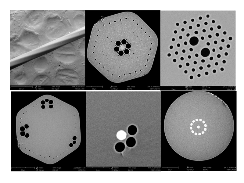
Fig. 1. Microstructured optical fibers of various constructions, twisted along the entire length by spinning the preform during drawing process . The twist period in the range from 1 m to 1 mm.
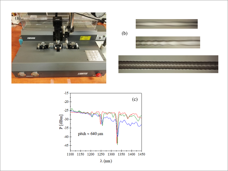
Fig.2. Lightel CW-500 workstation for local tapering/twisting of optical fibers with a period ranging from 1 cm to 500 µm (a), examples of twisted fiber structures (b) and transmission characteristics of three helical long-period gratings illustrating the repeatability of their fabrication process (c).
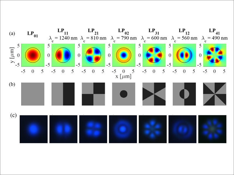
Fig. 3. Calculated field distributions of the modes propagating in the Corning SMF-28e fiber for the wavelength λ=475 nm. The black circle marks the diameter of the fiber core. The values of λc denote the cut-off wavelength of the given mode (a). Phase maps used to excite appropriate modes (b) and recorded modal field distributions at the fiber output for λ = 475 nm
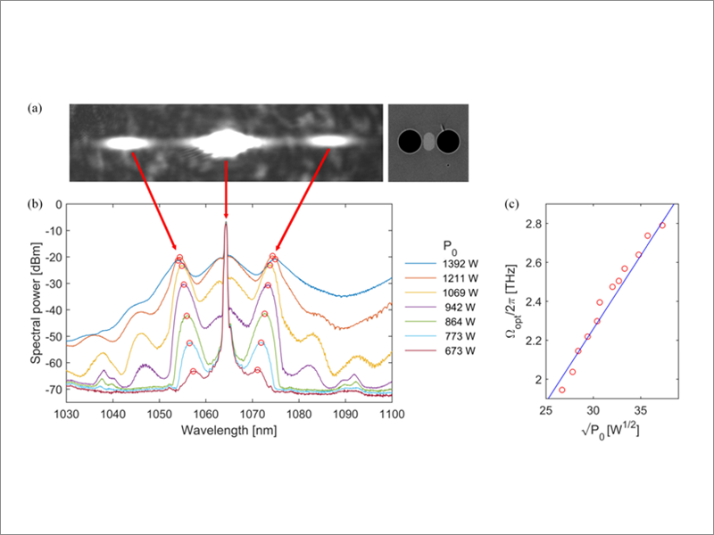
Fig. 4. Output signal spectrally decomposed by diffraction grating in horizontal direction for vertical orientation of the fiber elliptical core showing that the pump and the VMI sidebands propagate in the fundamental mode (a). Spectra registered for different peak pump powers P0 with the maxima of the first order sidebands marked with circles (b). Optimal detuning frequency of the first order VMI sidebands as a function of square root of the pump power measured (circles) and calculated (line) (c).
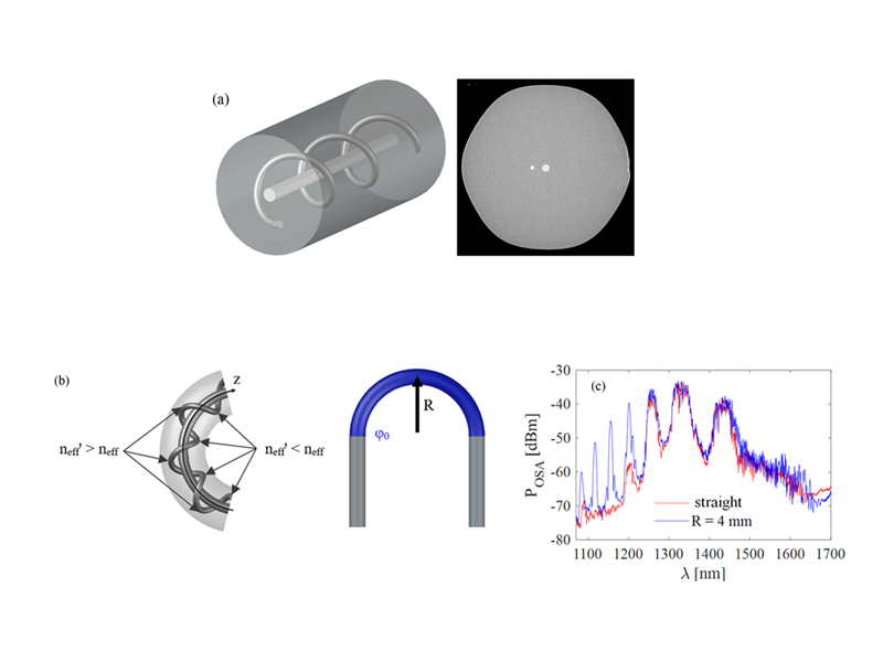
Fig. 5. Structure of the twisted dual-core optical fiber and electron microscope image of its cross-sections (a). Bent section of the twisted dual-core fiber with arrows indicating points with maximally reduced and increased effective refractive index of the mode propagating in the side core. U-shaped bend creating a long-period grating (b). Spectra recorded for the straight (red) and bent (blue) fiber when the central core is excited and the signal is collected from the side core (c).
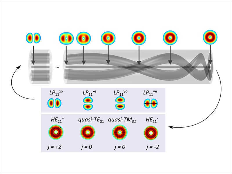
Fig.6. Explanation of the method of transformation of LP11 modes into vortex modes with different total angular momentum j in a gradually twisted birefringent PANDA fiber.
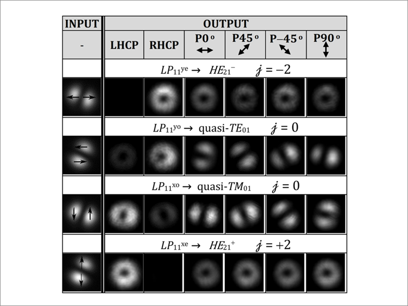
Fig.7. Experimentally observed transformation of LP11 modes to vortex modes in the gradually twisted PANDA fiber of a length of 3 cm. HE+21/HE-21 modes are nearly circularly polarized (average ellipticity angle |θ|=40±2o ) Averaged ellipticity of the quasi-TE01/TM01 modes is |θ|=16.5±2o . LHCP and RHCP indicate respectively left- and right-handed circular polarizers placed at the output of the mode converter; j indicates total angular momentum of respective vortex modes.